Passive filter designer drivers#
BLDC Pre Drivers and Integrated Solutions.Battery Management System: Monitor & Protection.Digital Isolators with Integrated Power.

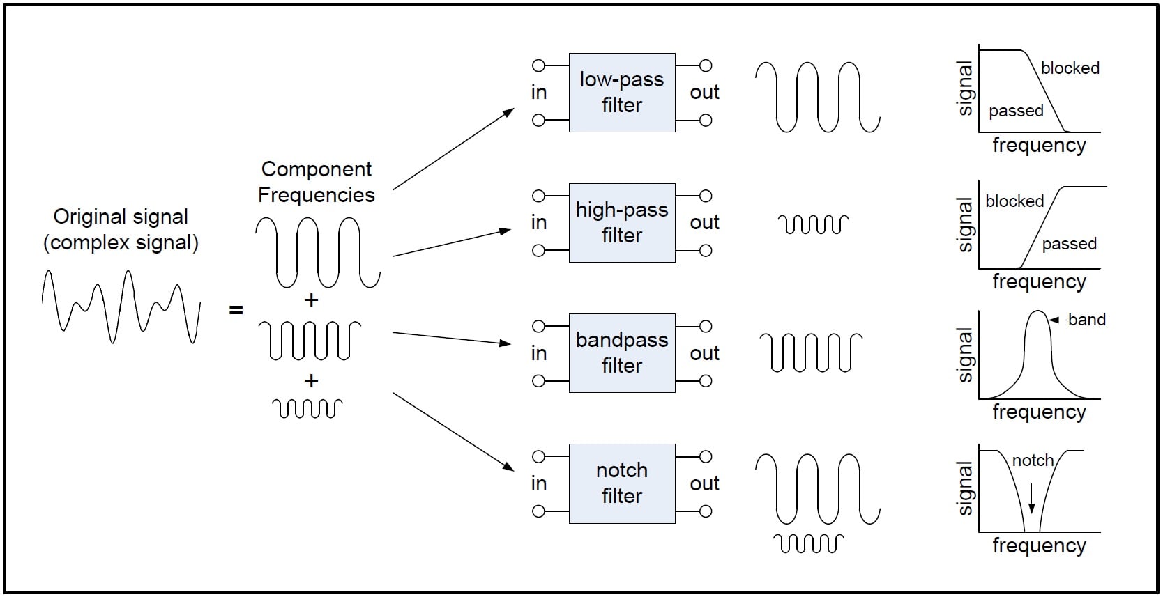
Multi Phase Controllers & Intelli-Phase.Also, a pole represents one RC stage in the circuit, as shown below. The slope of the line is called the roll-off of the transition. For a standard Butterworth filter, every pole adds -20 dB/decade or -6 dB/octave to the slope of the response. A pole is a root of the denominator of the transfer function. The slope of the transition region is related to the number of poles in the transfer function of the response, also known as the filter's order. Transition band: This represents the range ( f s - f c) of frequencies between the critical and cutoff frequencies.Stopband frequency, f s, is the frequency at which the maximum stopband ripple ( a 2) occurs.For certain filter types (Butterworth filters, for instance), at this frequency the amplitude of the response is of the nominal amplitude. Critical frequency, f c: This is the frequency at which the response leaves the passband ripple.The ripple is equal to the parameter a 2, which is determined by the circuit component attributes. Stopband ripple represents the variations in the stopband region.The ripple value is 2 a 1, where a 1 is a parameter dependent on the circuit components. These oscillations typically occur around the nominal value of 1.0, or at 0 dB, if the amplitude is expressed in decibels. Passband ripple: The variations or oscillations in the bandpass, or error band.Stopband: The range of frequencies where the output is zero or very small.Passband: The range of frequencies where the output has a gain.For instance, a notch filter can reject signals with frequencies between 50 Hz and 150 Hz.Įlectronic filters employ their own unique terminology to describe each device's filtration characteristics: Band-reject, or notch filters attenuate or suppress signals with a range of frequencies.
Passive filter designer tv#
They are common in TV or radio tuning circuits.

Band-pass filters attenuate or suppress signals with frequencies outside a band of frequencies.For example, a high-pass filter (HPF) with a cutoff frequency of 100 Hz can be used to suppress the unwanted DC voltage in amplifier systems, if desired. High-pass filters suppress or attenuate signals with frequencies lower than a particular frequency, also called the cutoff or critical frequency.

For example, a low-pass filter (LPF) with a cutoff frequency of 40 Hz can eliminate noise with a frequency of 60 Hz.


 0 kommentar(er)
